Clipper Foot Switch Wiring Diagram
You will see three (3) electrical terminal screws on the actual switching unit. Use two number 10 machine screws and two number 10 lock nuts when mounting foot switch to full guard.
13 Best Clipper Foot Switch Wiring Diagram

It features a cast aluminium housing painted alert orange with a splash resistant interior switch.

Clipper foot switch wiring diagram. Linemaster's ir wireless foot switch eliminates wires, providing a 360 degree redundant signal without the need for line of sight. We have the country clipper belts you need with fast shipping and low prices. Diagram free files related file of 3 position rotary cam switch wiring diagram.
A tube between the two foot switches conceals all internal wiring between them. Mercedes sprinter rv campervan conversion electrical wiring diagram. The wide treadle clipper switch offers the end user a 7
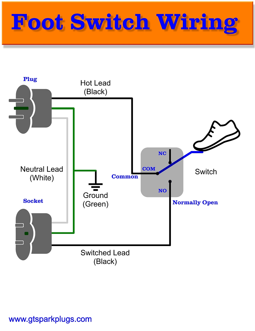
As the wiring shows we are really only wiring the black wires to the switch. Wiring diagrams sometimes called main or construction diagrams show the actual connection points for the wires. 9) now for the part where linemaster could have done a better job in their sub par wiring diagram.
9) now for the part where linemaster could have done a better job in their sub par wiring diagram. 2000 honda accord stereo wiring diagram. Swann h 264 dvr manual :
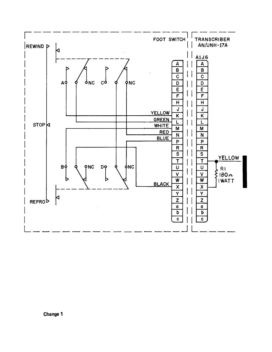
Connection to relay terminal 4 nc Country clipper offers parts and operators manuals to ensure years of trouble free operation and easy maintenance. Linemaster's mission is to provide a superior foot switch at an affordable price without compromise.
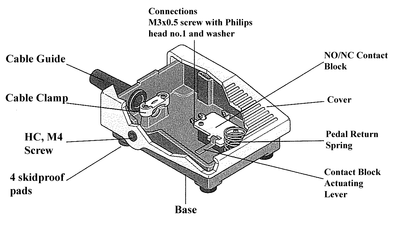
Ensure that none of the copper wire is left exposed or allowed to come into contact with any object within the foot switch housing. It is designed with an ergonomic shape and cast iron housing that will stand the test of time. Daisy bb gun repair manual graphics :
You will see three (3) electrical terminal screws on the actual switching unit. Miller hf 251d 1 manual : 18 rows replaces the clipper foot switch style.
Clipper foot operated switches are furnished with two 7/32 in. 2 wire plus shield cable, 2 on/off switches, a box and a trs plug. Most often, this is due to a lack of understanding of how the 3pdt switch operates.
Use two number 10 machine screws and two number 10 lock nuts when mounting foot switch to full guard. A conduit opening with strain relief connector is provided in the right foot switch. Motor ground is via another short wire with a ring terminal which goes on a mounting screw to floor.
Some rotary switches contain more than one circuit. Hf 251d 1 and hf 251 2 m. Xumlida brainpower motor controller 202003 wiring diagram.
Clipper f oo t swit ch www.linemaster.com the clipper foot switch was designed with an ergonomic shape and cast iron housing that will stand the test of time. Building one without led's is seemple. Switch wiring diagram rotary motor control selector switches off h a s phase conversion system smithy automate cnc machine tools 3 sd just bremas.
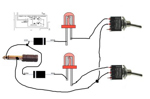
Shield is ground and goes to the sleeve of the trs plug and to one side of each switch, one wire to each switch and the other end to the left over connectors on the plug. The df200 is a dual foot switch with a connector tube to route the wiring from one side to the other, with a single cable exit point. Foot switch wiring diagram above is a simple diagram that shows how things get wired.
Clipper foot switch wiring diagram / f series foot. Up tp 93 off launching official electrical technology store shop now. The wiring colors in the usa are black for hot, white for neutral and green (or green/yellow) for ground.
Single 14ga wire from the switch to the heater. Country clipper model identification chart diagram a. Removed the top clipper switch cover.
I used an old extension cord and cut a short piece for the socket side. Clipper foot operated switches are furnished with two 7/32 in. The foot switches are mounted on a welded steel base with a center divider and bumper feet.
Click to view the foot switch safety warning or. Foot switch wiring diagram specifications to wire the actuator to the foot switch for double action (extention/retraction) make the connections between the foot switch, power source (battery), relay and actuator wires as follows: It connects to the motor thru an inline connector located under the seat a few inches away from the heater motor.
Ensure that none of the copper wire is left exposed or allowed to come into contact with any object within the foot switch housing. Great for applications such as pipe rollers, scissor lifts, lift tables, positioners, twin pedal, up/down. Equity alarm clock 30022 manual / equity by la cro.
Took pictures of where the wires were attached.

33 Foot Switch Wiring Diagram Wiring Diagram Database

Electrical Single Line Diagram — UNTPIKAPPS

Wanna Build a Timmy Overdrive? La Révolution Deux
[DIAGRAM] Diy Foot Switch Wiring Diagram FULL Version HD Quality Wiring Diagram
DIY Fender Princeton DSP 65 footswitch Dimitri De Franciscis' Blog

33 Foot Switch Wiring Diagram Wiring Diagram Database
Packard Wiring Diagram Wiring Diagram


13 Best Clipper Foot Switch Wiring Diagram
29 Foot Switch Wiring Diagram Free Wiring Diagram Source
Electrical Single Line Diagram — UNTPIKAPPS

Linemaster Foot Switch Tested 125250VAC 20A Clipper 632S Never Used 11' cord eBay

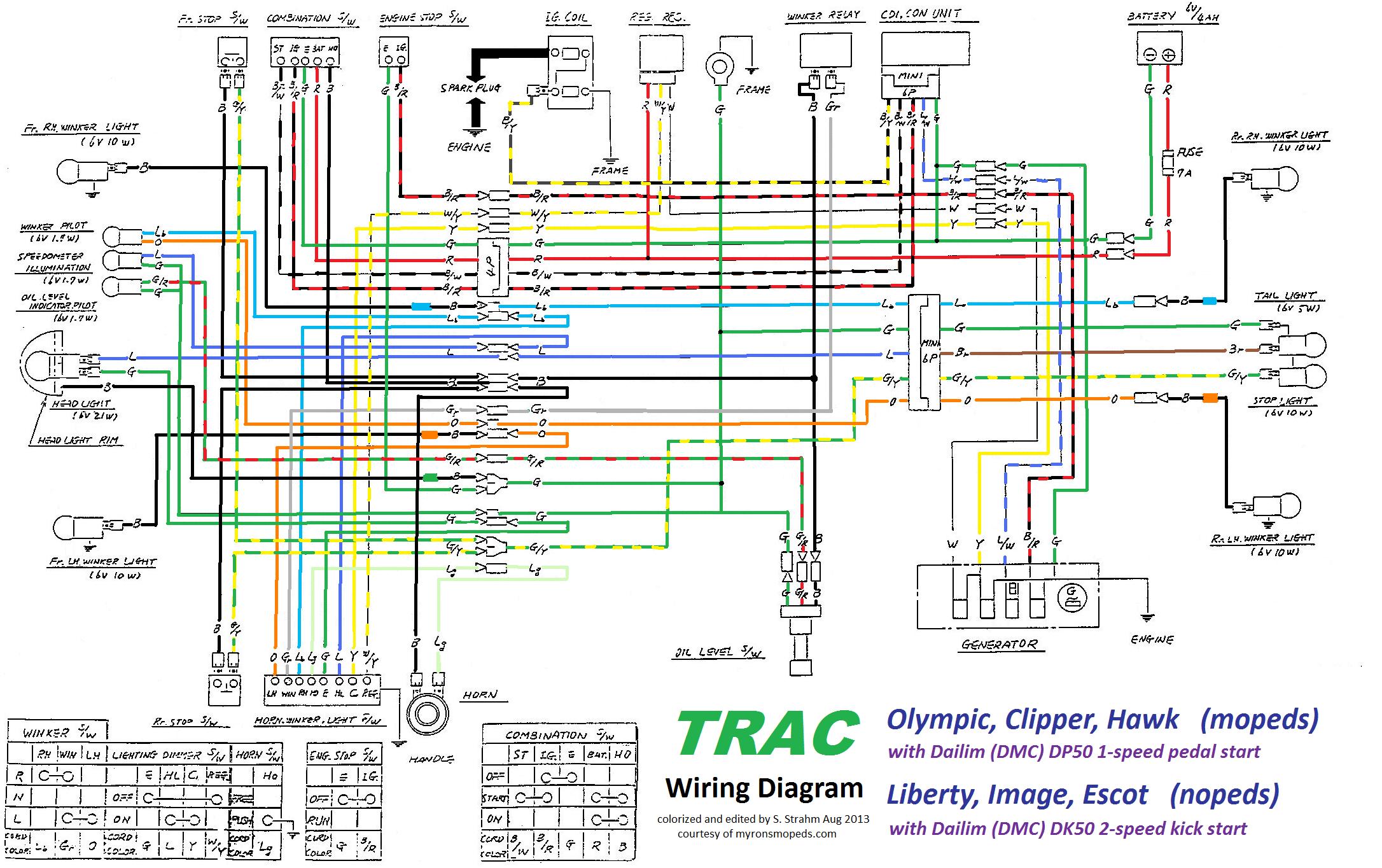
Trac Clipper headlight blinks with signals — Moped Army
Wiring Diagram Momentary Switch KIMRAESHIELDS
DIY Foot Switch GTSparkplugs

• View topic Order Switching Toggle
31 Foot Switch Wiring Diagram Wiring Diagram Ideas
33 Foot Switch Wiring Diagram Wiring Diagram Database
Born on the Bayou Build Your Own Kustom Harmonic Clipper Tone Report


[DIAGRAM] Diy Foot Switch Wiring Diagram FULL Version HD Quality Wiring Diagram ONLYFOOTBALL.FR